Description
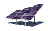
This is an easy-to-assemble kit for ground mounted PV solar array holding 40 panels in a five vertical (landscape) by eight across setup at 20 degree tilt. The kit includes all the solar mounting hardware needed to install the system (steel posts, rails, clamps and hardware). This 22 post kit does not include solar panels, cables, inverters or concrete. Designed for standard loads up to 110 mph wind in Category C exposure, and 20 psf snow at 20 degree tilt. Fits standard residential or commercial XL modules up to 40 x 79 inches. 25 year limited warranty from IronRidge. PE certified dry stamped design letter available for most states. Order online or PHONE 888-498-3331
FEATURES
- Easy to assemble
- Kit includes Sched 40 2" galvanized steel posts, IronRidge rails, clamps and hardware
- Holds 5 vertical x 8 across solar panels at 20° tilt
- Designed for up to 110 mph Wind, Category C location, and 20 psf Snow load
- Requires 22 concrete foundations 4ft deep X 16" diameter (cement not included)
- PE Stamped design letter available for most states
- No Soil Testing Required
- 25 Year Limited Warranty from IronRidge
Videos
-

Ground Mount for Open Fields // Solar Webinar
Ground Mounted solar arrays often appear very simple, but thei...
-

Make Solar Stronger // Ultimate Racking Test
IronRidge pit their XR rails against the competition by drivin...
-

IronRidge Solar UFO® // Universal Fastening Object
It's not a clamp. It looks better, installs faster and simplif...
Parts / Specifications
Array size: |
40 solar modules, landscape |
Layout: |
5 rows x 8 columns, landscape |
Tilt: |
20° fixed |
# North Piers: |
11 |
# South Piers: |
11 |
N-S Pier Span: |
7' 6" |
E-W Pier Span: |
5' 1" |
E-W Cantilever: |
1' 3" |
N Edge Ground Clearance: |
1' 4" |
S Edge Ground Clearance: |
7' 2" |
Dimensions when Assembled: |
54' W x 16' 9" D x 7' 2" H (above grade) |
Maximum Module Dimensions: |
40" x 79" |
North Pier dimensions: |
8' 4" total; 5' 8" above grade, 2' 8" below grade |
South Pier dimensions: |
5' 2" total; 2' 5" above grade, 2' 8" below grade |
FOUNDATION REQUIREMENTS: |
FOUNDATION REQUIREMENTS |
Type: |
Concrete (user supplied) |
Hole Diameter: |
16" |
Hole Depth: |
48" |
Pipe Size: |
2" |
Pipe Type: |
Sched 40 galvanized steel tubing |
Diagonal Bracing: |
Not required for design |
FOUNDATION DESIGN LOADS: |
FOUNDATION DESIGN LOADS |
Wind Exposure: |
Category C |
Wind Speed: |
110 mph |
Snow Load: |
20 lbs psf |
Shear: |
500 lbs |
Moment: |
1,250 ft-lbs |
Uplift: |
-894 lbs |
Code: |
IBC, ASCE 7-16 |
Certification: |
UL 2703 |
MATERIALS LIST: |
MATERIALS LIST |
Total Pipe Length: |
255' |
Vertical Posts: |
22 (11 North, 11 South) |
Cross pipes: |
2 |
Rails: |
16 XR-1000-168 |
Top Caps for 2" pipe: |
22 |
Rail Connectors for 2" pipe: |
32 |
Grounding Lugs: |
1 |
Universal Fastening Objects: |
96 |
UFO stopper sleeves: |
32 |
Cement: |
4.6 cubic yards (user supplied) |
Installation Instructions
DOWNLOADS
![]() IronRidge ground mount datasheet
IronRidge ground mount datasheet
![]() IronRidge ground mount tech brief tubing
IronRidge ground mount tech brief tubing
![]() IronRidge ground mount installation manual
IronRidge ground mount installation manual
![]() IronRidge ground mount tech brief suspending pipe in concrete
IronRidge ground mount tech brief suspending pipe in concrete
Tools Required to Install Ground Mount Solar Array
- Post Hole Digger or Powered Auger
- Socket Drive (7/16”, 9/16”, and 1/2” Sockets)
- Torque Wrenches (0-240 in-lbs and 10-40 ft-lbs)
- Transit, String Line, or Laser Level
- 3/16” Allen Head
FOUNDATIONS
ALL CONCRETE WORK SHALL CONFORM WITH THE REQUIREMENTS OF ACI 301 AND ACI 318. CEMENT PER ASTM C150, TYPE II. AGGREGATE PER ASTM C33. CONCRETE SHALL BE READY MIXED IN ACCORDANCE WITH ASTM C94 AND SHALL BE DESIGNED FOR A MINIMUM 28 DAY. COMPRESSIVE STRENGTH AS FOLLOWS: FOUNDATIONS of 3,000 PSI* (*DESIGNED FOR 2,500 PSI)
1. NO SOILS REPORT PROVIDED. FOUNDATION DESIGN IS BASED ON MINIMUM IBC SOIL BEARING VALUE = 1500 PSF PER IBC TABLE 1804.2. DRILLED SHAFT FOUNDATIONS SHALL BE BUILT IN UNDISTURBED SOIL OR COMPACTED FILL MATERIAL NOT LESS THAN 12" IN DEPTH. THE MINIMUM DEPTH OF FOOTINGS BELOW THE UNDISTURBED GROUND SURFACE SHALL BE 12".
2. THE STRUCTURAL ENGINEER IS NOT RESPONSIBLE FOR ANY GEOTECHNICAL ASPECTS OF THIS PROJECT. IT IS RECOMMENDED THAT THE OWNER RETAIN A REGISTERED GEOTECHNICAL ENGINEER TO CONDUCT A GEOTECHNICAL INVESTIGATION AND PREPARE A REPORT WITH RECOMMENDATIONS FOR FOUNDATION AND EARTHWORK PROCEDURES.


